 |
When installing prepping and riveting the horizontal stabilizer skins and inboard ribs, be sure not to dimple or rivet where the empennage fairing is supposed to attach. If you're really forward looking you might even drill these for the correct screw size, dimple for screws and nutplates, and install the nutplates. The same goes for the skin and bottom rib of the vertical stabilizer. |
 |
don't bend the trailing edge bend too far. I ended up turning two elevator skins into scrap metal trying to do the trailing edge bends. |
 |
When bending the tabs that close off the triangle where the trim tab fits:
|
 |
BUY ONLY SINGLE FLUTE COUNTERSINK BITS! The three flute variety can chatter easily resulting in a countersink hole that looks like this one. |
 |
Examine the end of your countersink cage before using it. I bought some off eBay and the face wasn't machined completely smooth. Before I realized what was going on, the face left some marks in my spar flange. I had to file these out. |
 |
Don't make clips like this to support the fuel vent line... |
 |
...make them like this instead. The design that Van's shows (pictured above) require a slight dip in the line to go through the clip. It sure seems like a place for moisture to collect which worst-case could freeze, clog the vent line, and cause fuel starvation. |
 |
If you need to transfer drill through a hole that's already been dimpled, use a hinge bit. It will center the drill in the dimple perfectly. |
 |
When attaching the wing jig to the aft end of the outboard wing ribs, be mindful of the hole pattern that will need to be match drilled through the outboard aileron bracket. Here you can see the series of five holes that will be drilled for attaching the aileron bracket, but the 3/32 hole I drilled for attaching the wing jig is causing a hole spacing problem. Poor planning. :-( |
 |
Careful planning will allow a straight conduit run through the wing and into the fuselage. I haven't tested this yet, but I believe the green dot is the best place to position a conduit if you want it to run uninterupted into the fuselage. |
 |
Be sure not to dimple the inboard most wing ribs and their associated holes in the wing walk doubler and top and bottom main skins where the fuselage fairing attachment points are. If you're really forward looking you might even drill these for the correct screw size, and drill and dimple for the nutplates that go here. As a side note, you have to rely on the preview plans to determine which nutplates will go here since the full size plan with this detail on it comes with the fuselage kit. My set of preview plans called for K1000 nutplates on the top of the wing. That's actually wrong. They should be K1100 nutplates to accept countersunk screws. |
 |
Unibits do not stay centered unless the bit is rigidly chucked in a drill press and the work piece is rigidly clamped to the table. Here are two conduit holes that were drilled with a unibit. The pilot holes were perfectly matched, but after using the unibit, the hole has drifted 1/16 inch. |
 |
Pay close attention to the plans when assembling the aileron brackets. Not all these rivets are supposed to be universal head rivets. Some are supposed to be flush. And to be even trickier, some of the heads need to be on one side or the other. |
 |
When painting, if you catch a glare in the surface that you're priming, you can actually watch the amount of primer that's getting applied to the surface so that it completely wets the surface and all the tiny little droplets flow together into a nice uniform coat. It's really very visible and controllable if you just pay attention to the reflection of light on the surface of the paint. |
 |
The end of the angles which attach the aileron brackets to the rear spar probably need a slight radius filed on them. Otherwise, the end of the angle rides somewhat on the rear spar flange bend radius which prevents the angle flange from sitting tightly against the rear spar web. |
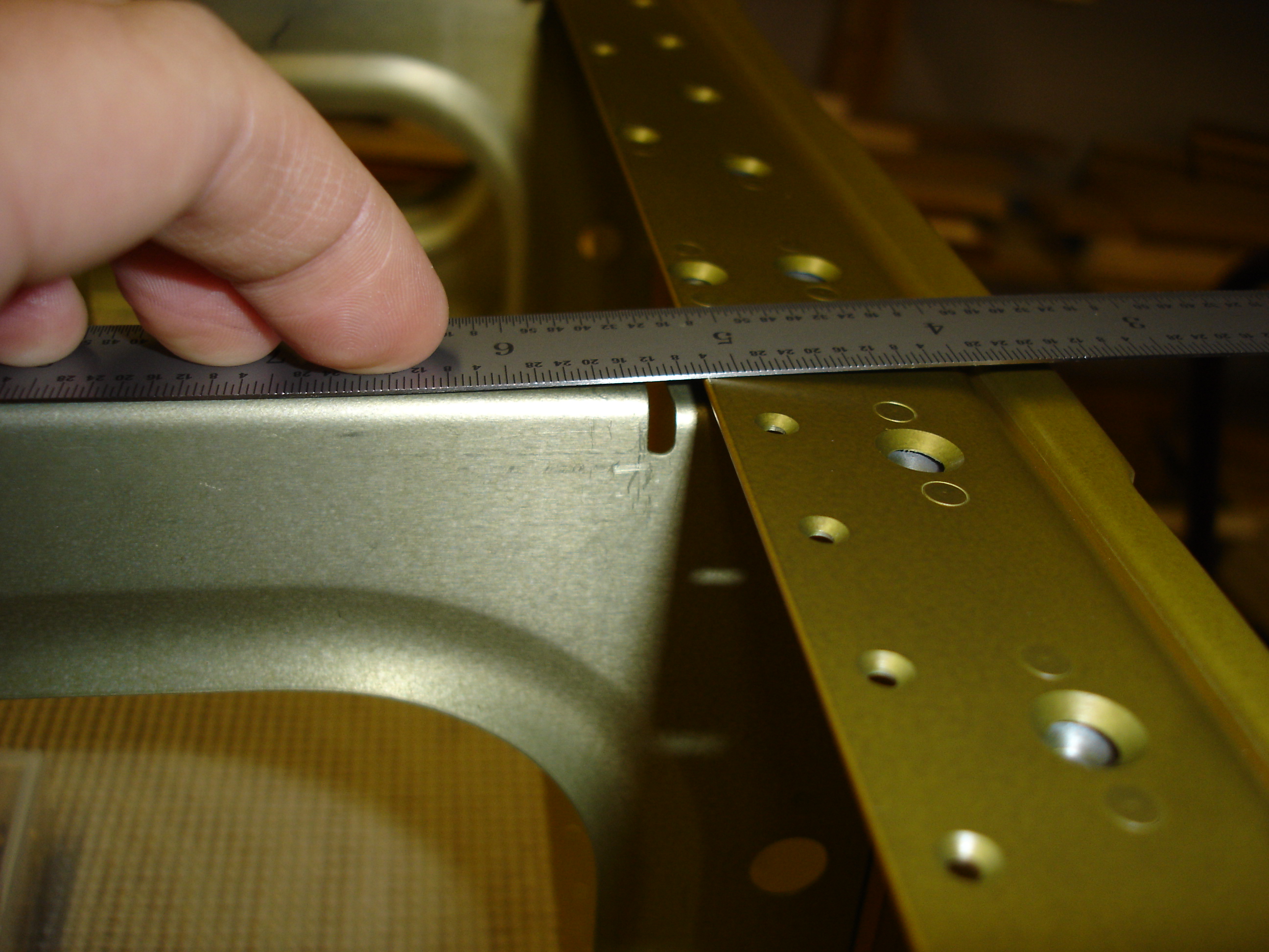 |
Check your spar flange bend angles before doing any work on them. Mine were out of spec and I didn't discover it until after riveting on the main ribs. I was able to fix them, but it was a lot of work. After a talking with Scott at Van's, I learned that the spar flange angles are: Top flange 88.5 +/-.5 degrees. Bottom flange 89 +/-.5 degrees Measured between flange and web (in the corner where the main ribs sit) Scott indicated that they have had several spars with this problem. Apparently the spar channel is OK until it is assembled with the top and bottom bars. This causes the flanges to open up a bit. Scott recommended the same fix they use at Van's when they encounter this problem...cut a slot in a 2x4 and use that as a lever to tweak the flanges into positon. |
 |
Check out Sat May 5 2007 for a decent explanation of how to drill out rivets without enlarging the hole at all. |
 |
If possible, always put the manufactured head on the thinner material. If you put the shop head on the thin material side, it will pucker as you see here. |
 |
Don't attach the aileron brackets until after the top main skins are on. There are a couple skin to rear spar rivets that you can't get to with these brackets on. |
 |
When mounting nutplates, if you drill the screw hole to final size first, you can cut a screw short (so you don't have to screw it in much) and use it with an actual nutplate as a drilling template to locate the nutplate attach holes. Who needs those expensive nutplate drilling jigs, anyway?! :-) |
 |
See Tue May 29 2007 for a way to dimple (or fixup a dimple) in a spot where there is no squeezer or c-frame access. Be sure to use low pressure (around 10psi). |
 |
Don't dimple the holes that attach the tank skin to the baffle. The rivets are really close to the spar at the inboard end and having dimples makes it even closer. There appears to be enough room for dimples here (not done with tanks as of this writing), but you need a special dimple die to dimple the baffle. I'll try to remember to update this to let you know how the tanks came out with dimpled baffles. Update: Dimpling the holes that attach the tank skin to the baffle worked really nicely. I actually think I'd do it this way if I did it over again. The trickiest part is dimpling the baffle. The flange bend is really close to the holes so you have to buy a special small diameter dimple die. Cleaveland Tool sells them. I actaully talked Mike Lauritsen into making me a small diameter version of the tank die so that these dimples would be the same as all the others on the tank (which were done with the Cleaveland tank dies). |
 |
Tweak the flange of the flap braces that rivets to the bottom skin at their inboard end so it doesn't cause the skin to flare upward when riveted. |
 |
Don't forget to put the ferrule and nut on the vent line before flaring or installing the inboard most rib in the tanks. |
 |
Here's a nifty trick I learned from my mom many years ago (she used to be a nurse). If you want to reuse a glove that you peeled off previously and now it's inside out, just get the glove flipped the right way and blow into the opening. All the fingers will pop out and you can avoid all the pulling and tugging. |
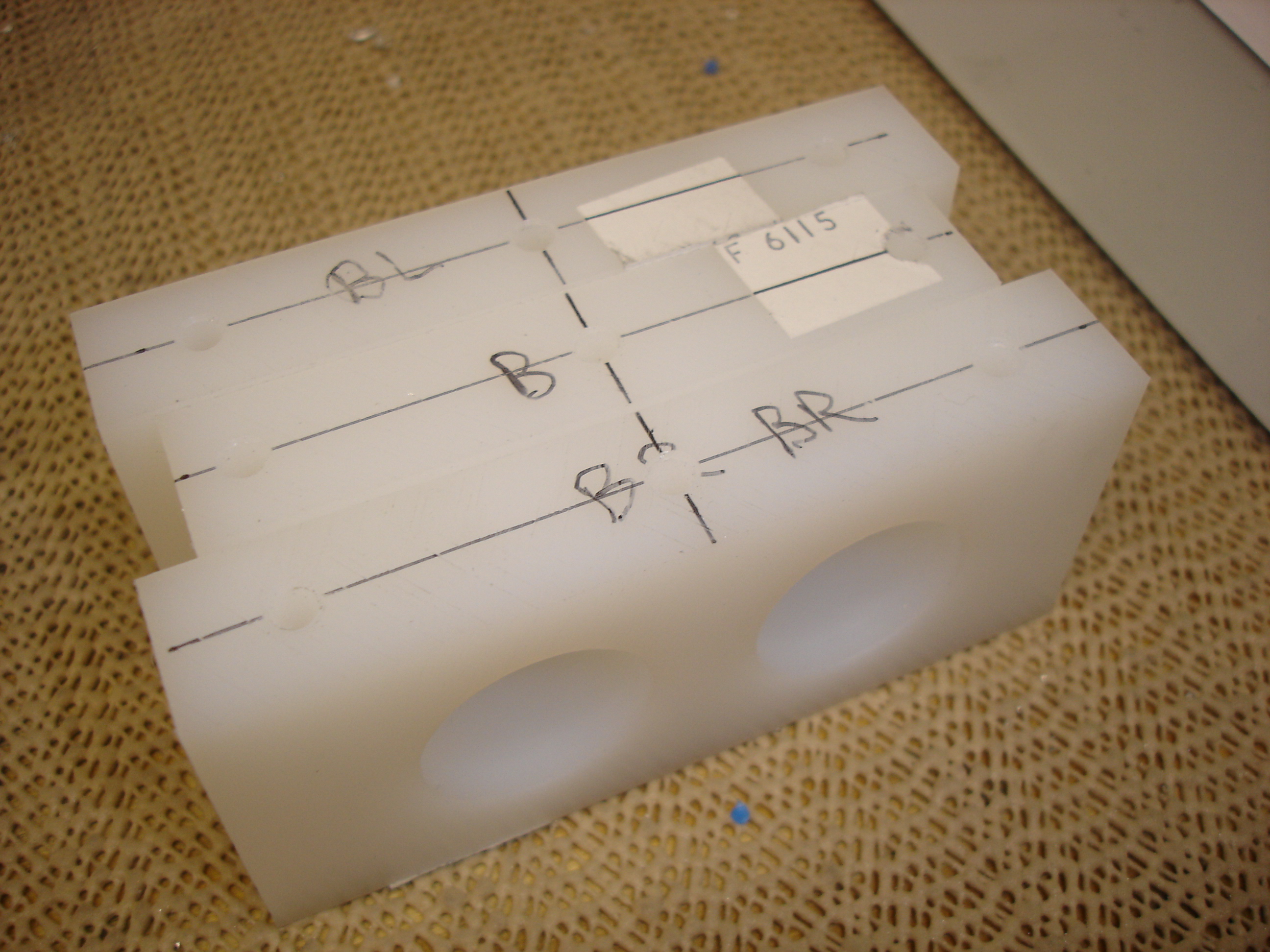 |
When laying out multiple positions of the rudder pedals, it's much easier to avoid overlapping holes if the outboard bearing blocks have the same bolt hole spacing as the center block. I used the 3 1/2 inch spacing (which was specified for the center block) for all three blocks. |
 |
When fitting the F-695R & L gussets, you'll end up with a gap between the gusset and the firewall stiffener. Fabricating a little wedge like this will make it all fit together much more nicely. |
 |
If the thought of your lower fuselage oil canning like this is concerning to you, you may want to consider adding extra stiffeners to the tailcone bottom skin. |
 |
When working on the seat backs, there's a piece of 3/4 x 3/4 x 1/16 aluminum angle to which you need to apply a radius to the vertex of. If you have a router, using a 1/8 inch radius roundover bit makes short work of creating the correct radius. You can round over both pieces in a matter of minutes instead of an hour or so of agonizing filing. Just take care to use some scrap at the left and right ends of your angle so that when the router base slides past the end of the angle, it doesn't tip and gouge your work piece. Don't ask me how I know about that. :-( |
 |
Be aware that one hole on each of the vertical seat rails is not inline with the rest. If you drill them all inline (like I did), you will end up with bad edge distance for the hinge attachment. |
 |
In areas where you're riveting a skin to a rib flange, but the web of the rib has been doubled up such over the inboard most flap rib, or where the bottom fuselage skin overlaps the side fuselage skins, be sure to file back the edge of that doubled-up material so that when you're driving the rivets, the rivet gun doesn't pound the skin into the edge of that doubled-up material. See Mon Dec 3 2007 and Mon Feb 20 2023 for examples where this has caused problems on my build. On the second example (the fuselage bottom skin), this ended up in cracks to the bottom skin which prompted me to remove and replace this skin. What a pain. |